Ender 3 S1 “Sprite” Extruder Review and Disassembly
The Ender 3 S1 and the CR-10 Smart Pro include a completely redesigned direct drive extruder and hot end, known as the “Sprite” extruder. Since this hot end is so different from other Creality 3D printers, we wanted to take it apart to get a better sense how it works, and how difficult it will be to repair. In this article, we’ll go through the process of how we took it apart, and take a look at how its built.
Note: Creality Experts receives a commission for items you purchase from this page, at no additional cost to you. For more information, please see our affiliate link policy.
First Impressions
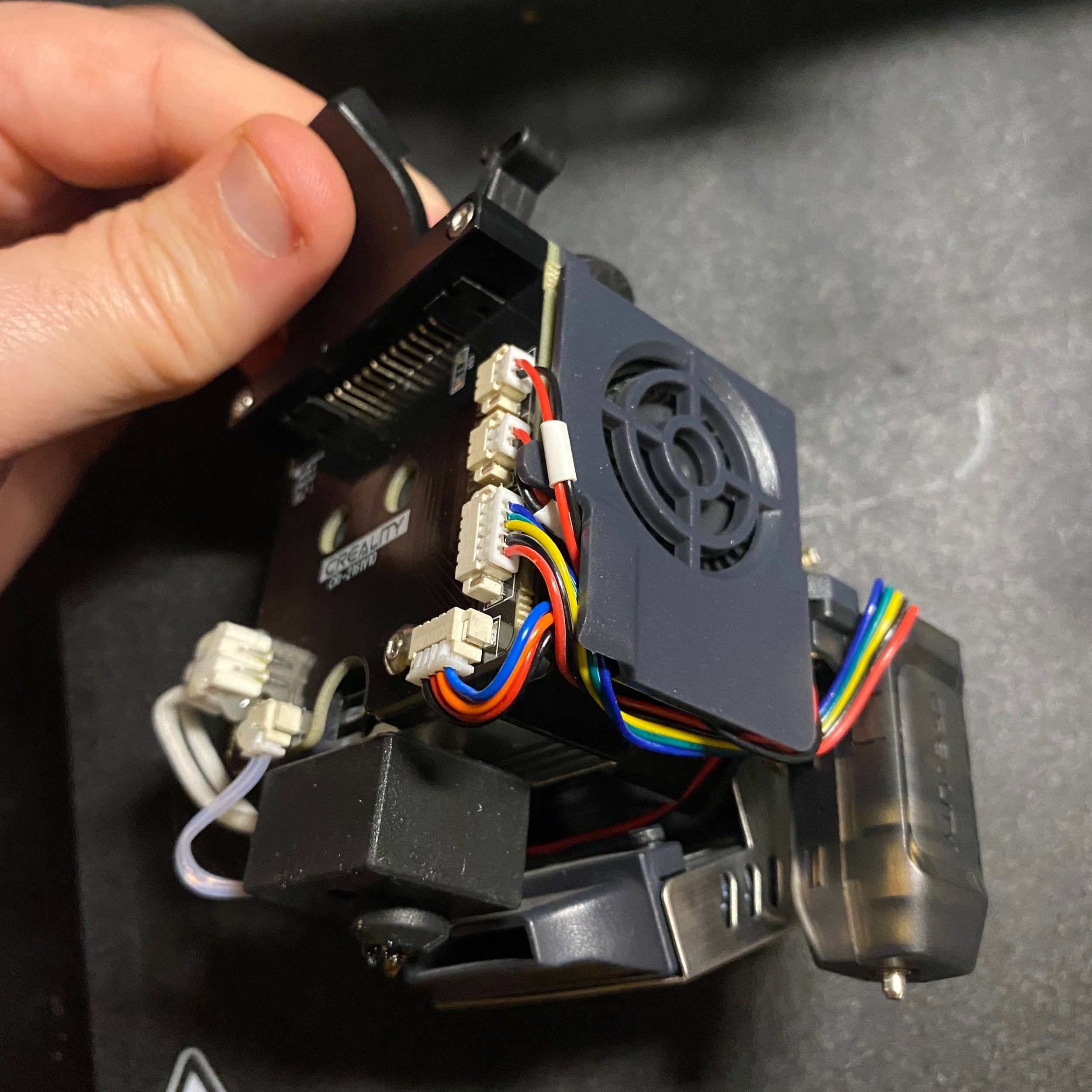
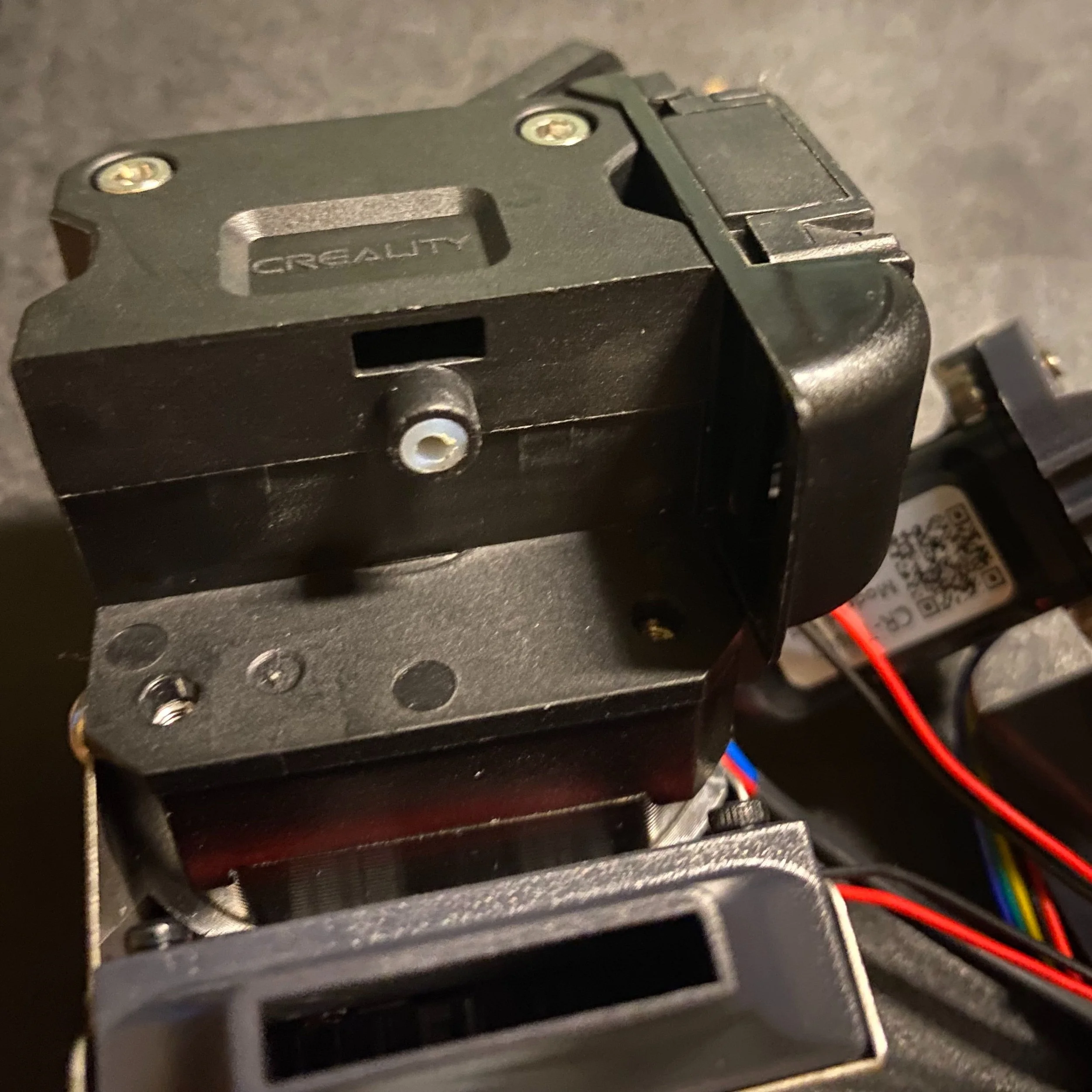
The “Sprite” hot end packs a lot into a pretty compact package, including the extruder, hot end, and CR-touch leveling sensor.
Note: The photos in this article are from the Ender 3 S1 (View on Amazon). This extruder is also featured on the CR-10 Smart Pro (View on Amazon), using a slightly different all-metal construction, which allows for higher printing temperatures.
The hot end comes fully assembled when you purchase the printer, and it’s a complex device since it contains both the extruder and the hot end. Most other Creality printers use a Bowden extruder, where the hot end and extruder are separate components.
When looking at the hot end, the first thing we noticed was the breakout board, which provides plug-in connection interfaces for all the hot end and extruder components. The cabling is sized so that it all fits very well within the assembly. We initially thought that this would make replacing these components much easier than other printers, which require splicing wires. However, as of this writing, thermistor and heat cartridges with these connectors are not readily available to purchase, so replacement would still require wire splicing. We hope to see this change as the S1 becomes more popular.
Some other components, such as the CR-touch auto leveling sensor and the fans, come with the plug-in connectors by default and would be easy to replace. However, it may be a challenge to find a place for the extra length of cable included with a generic replacement part.
Detaching the Heat Sink
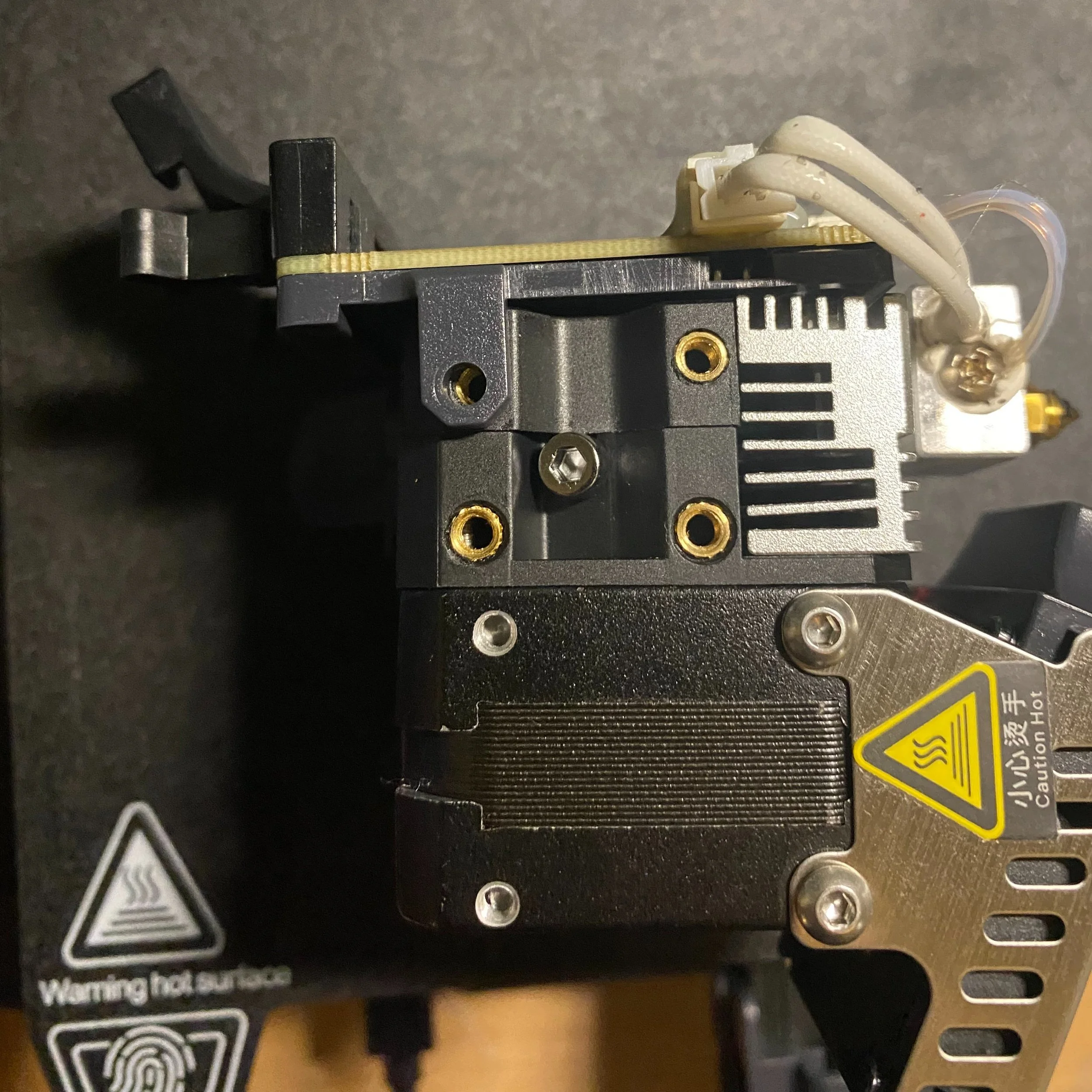
To detach the heat sink from the extruder assembly, remove the two long screws on the breakout board side. You’ll need two different sized Allen wrenches to remove these screws. Removing the heat sink allows you to access the small section of PTFE tubing within the hot end, which is a wear item that may need to be replaced after many hours of printing. We were glad to see that this was easily accessible without fully disassembling the hotend.
A second small section of PTFE tubing is used between the extruder assembly and the heat sink, but this piece is unlikely to degrade since it is completely in the cold portion of the assembly. We were glad to see that these sections of PTFE were separated, since it will ensure that any retraction movements by the extruder do not cause any movement of the hot end tube, which can cause filament to get stuck between the tube and nozzle and cause jamming. This is also less of a concern on direct drive extruders since far less retraction is needed.
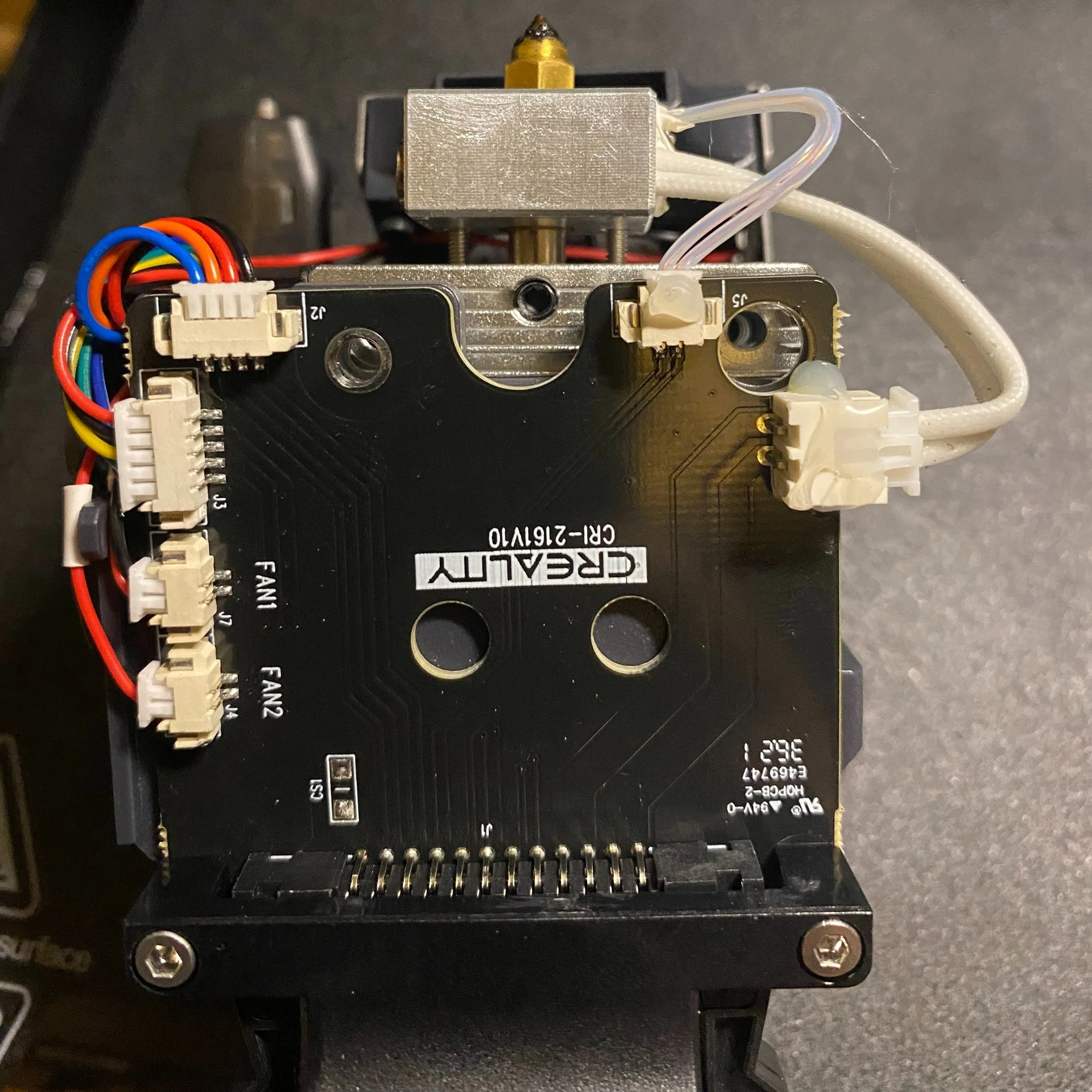
To detach the heat sink, remove the two long screws on the breakout board side.
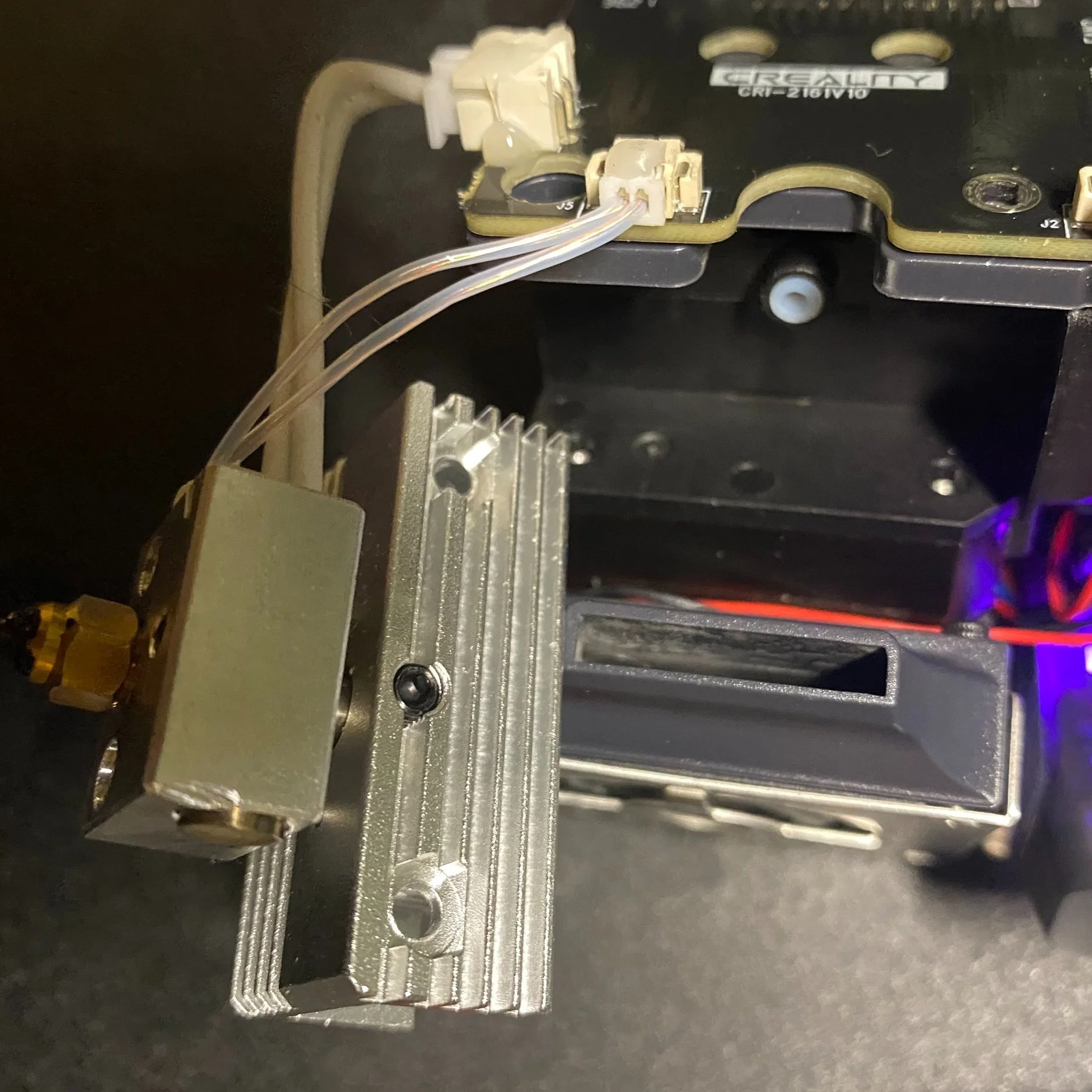
The removed heat sink (and heater block).
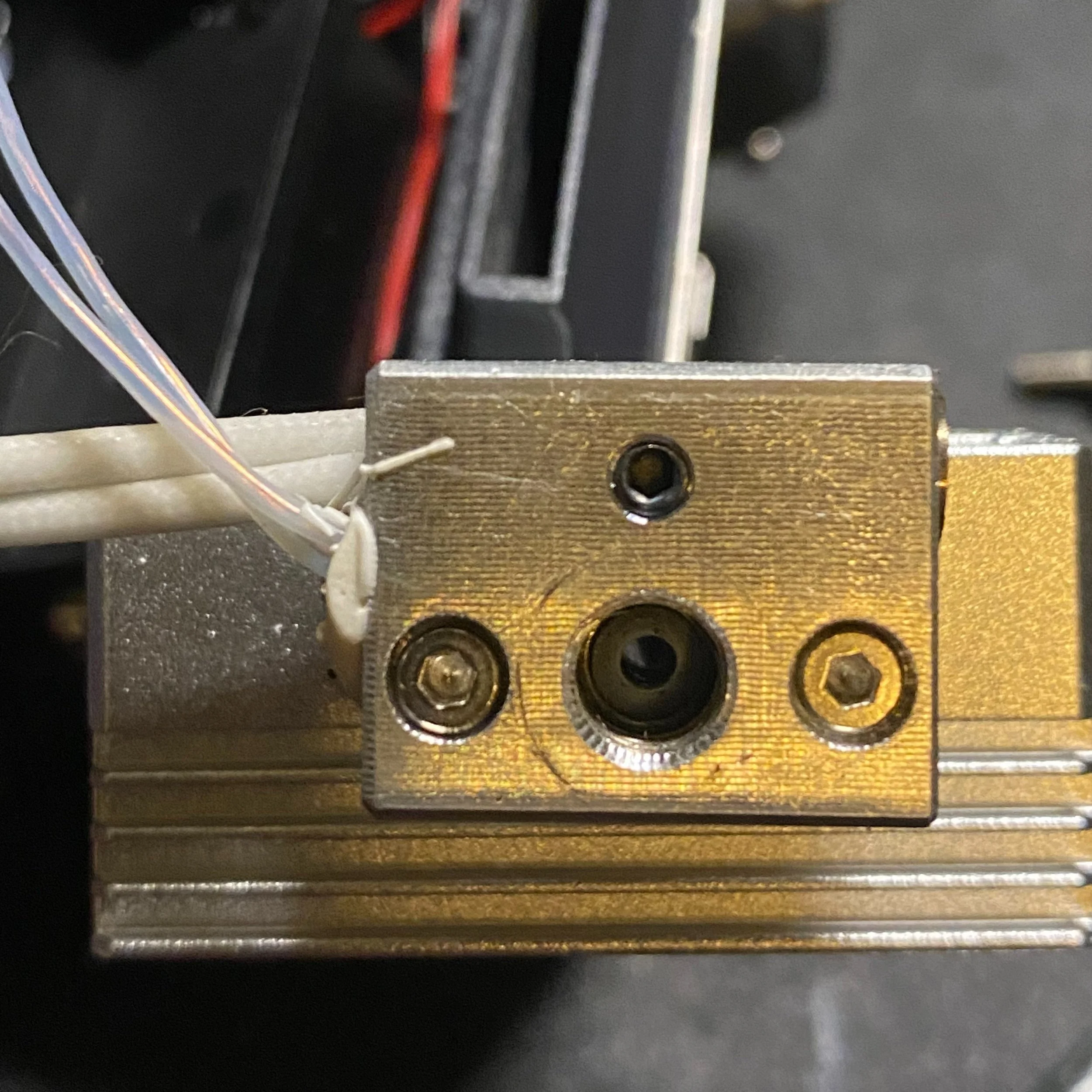
Removing the nozzle exposes the PTFE tube, which may need to be replaced after a lot of printing. Note: the CR-10 Smart Pro version is all-metal, and does not have PTFE here.
A second section of PTFE is used between the extruder and the heat sink.
Removing the Plastic Enclosure
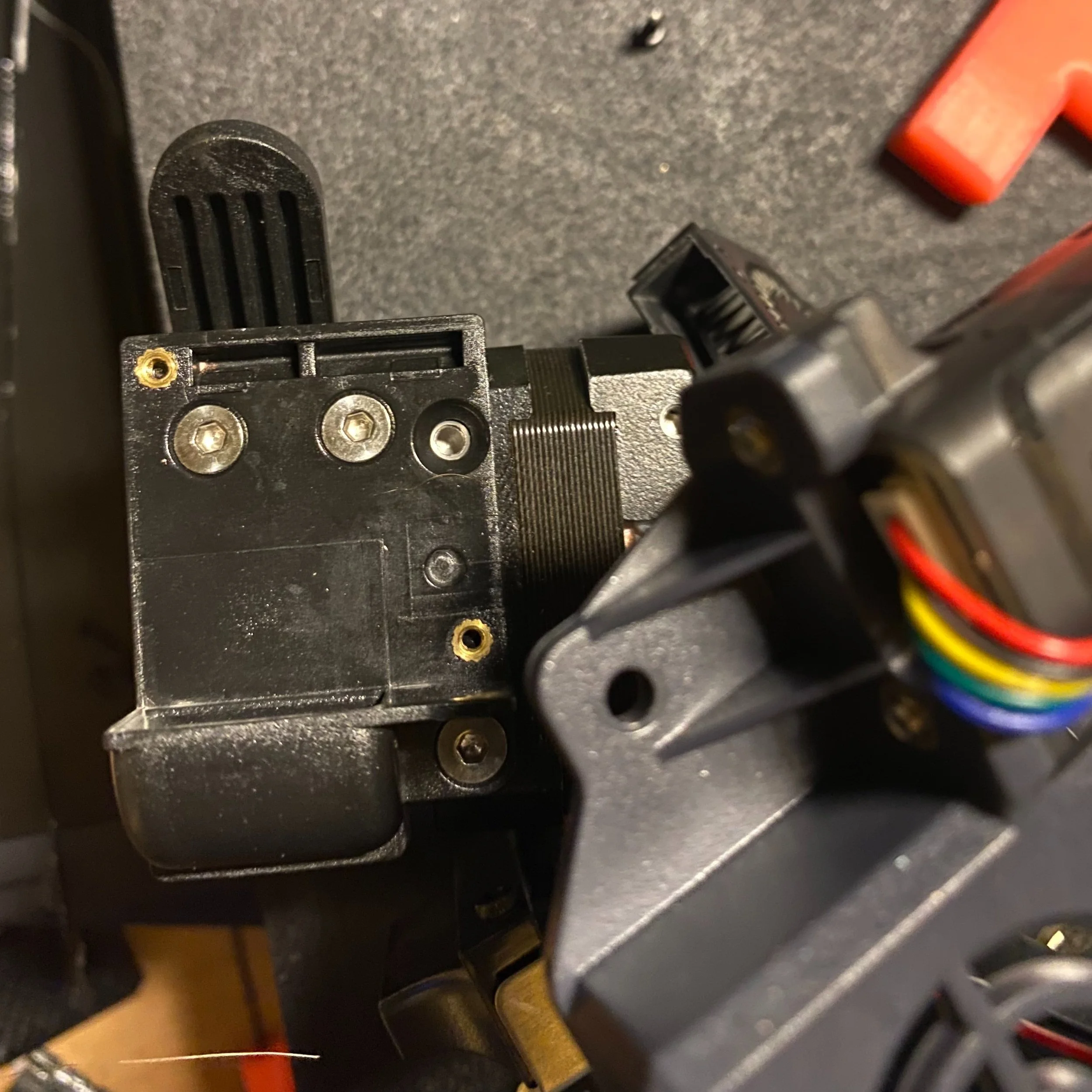
Next, we detached the plastic enclosure, which is attached by two small screws. One is located on the left side of the hot end and the other is above the CR-touch sensor. Once these are removed, slide the inner assembly downward to release it from the enclosure. As you slide the assembly downward, be careful to not pull on any of the wires.
The first screw holding the enclosure attaches to a small plastic tab.
The second screw is above the CR-touch sensor.

The enclosure can now be removed, but be careful not to pull the wires as you remove it.
Opening the Extruder Mechanism
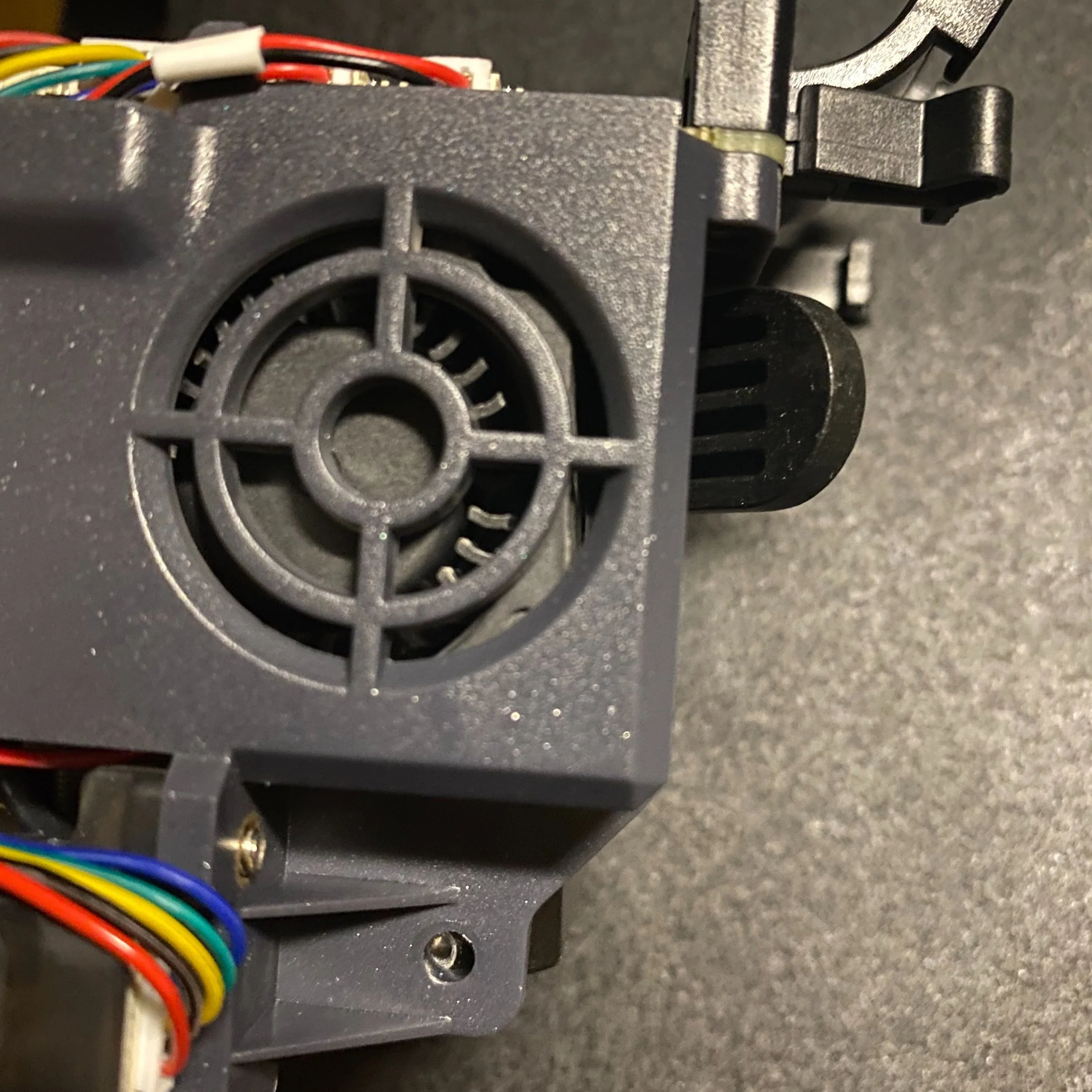
Remove the small fan, then remove the 3 screws shown here to open the extruder assembly.
To access the filament path inside the extruder, first remove the small cooling fan using a 1.5mm Allen wrench, which exposes all of the screws holding the extruder together. Remove these 3 screws, then remove the fan duct bracket. Once the fan duct is removed, the front plate of the extruder can be removed, exposing the inner mechanism. We were concerned that this might release tension on the springs, but fortunately the spring is held in place even after removing the front plate.
We were interested to see how well supported the filament path is, which is important to prevent jamming when printing flexible filament. We were pleased to see that there is nearly no gap between the filament path and the extruder gears. The extruder mechanism also looks well built, using a dual gear drive system which pushes the filament from 2 sides. The geared down extruder motor gives the extruder more torque and control.
That said, we are a bit concerned that the lever arm assembly is made of plastic, since it is under continuous tension from the spring to hold the filament in place. We have seen issues with Bowden style 3D printers that use plastic extruders, such as the Creality Ender 3 V2. If this piece were to crack, it would be hard to discover since the parts are fully enclosed. On a positive note, the lever arm is much shorter on this extruder, so less force is acting on the plastic and it is less likely to fail, but we still wish that a metal part were used here.
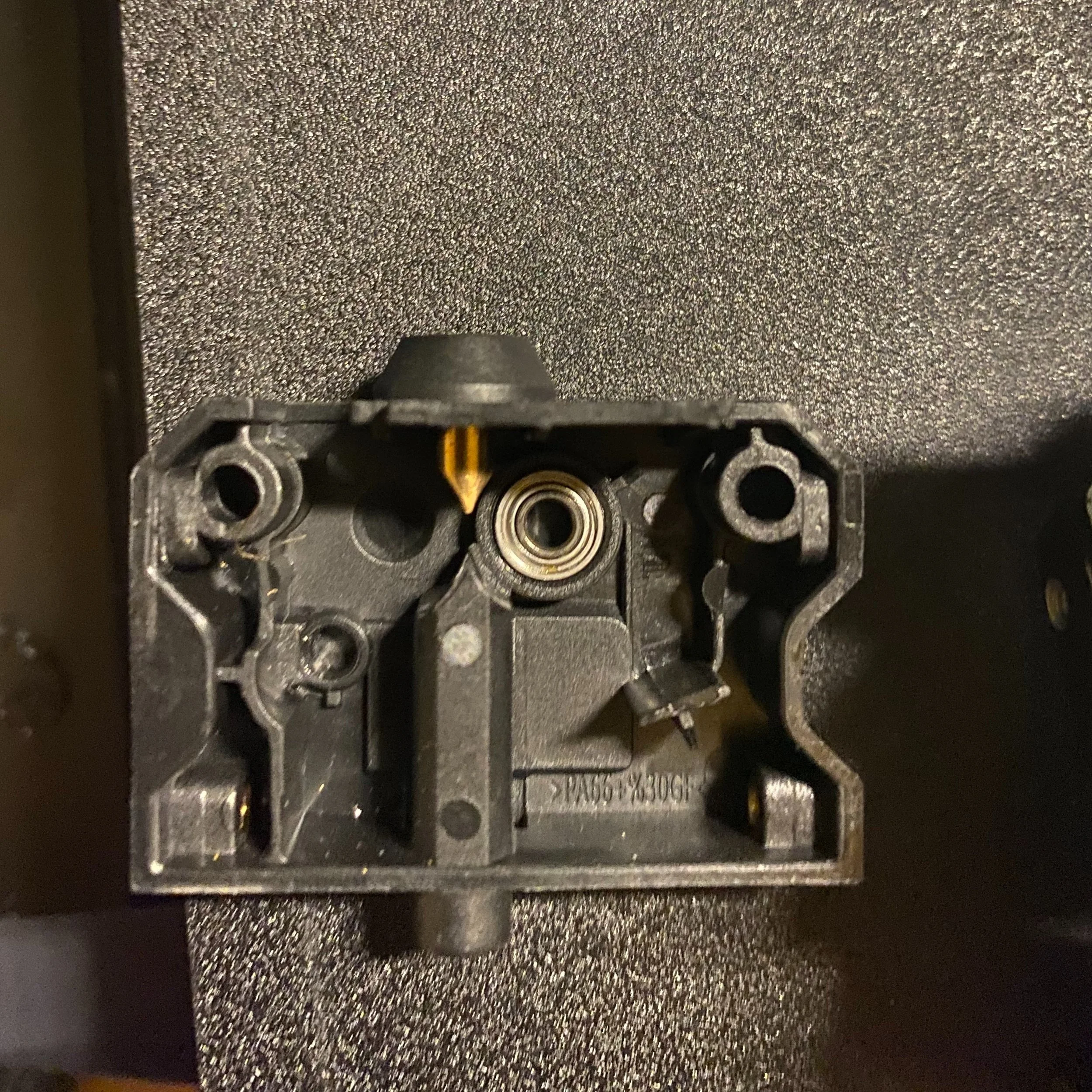
The filament path is on the extruder cover, and does a good job of enclosing the filament path all the way up to the extruder gears.
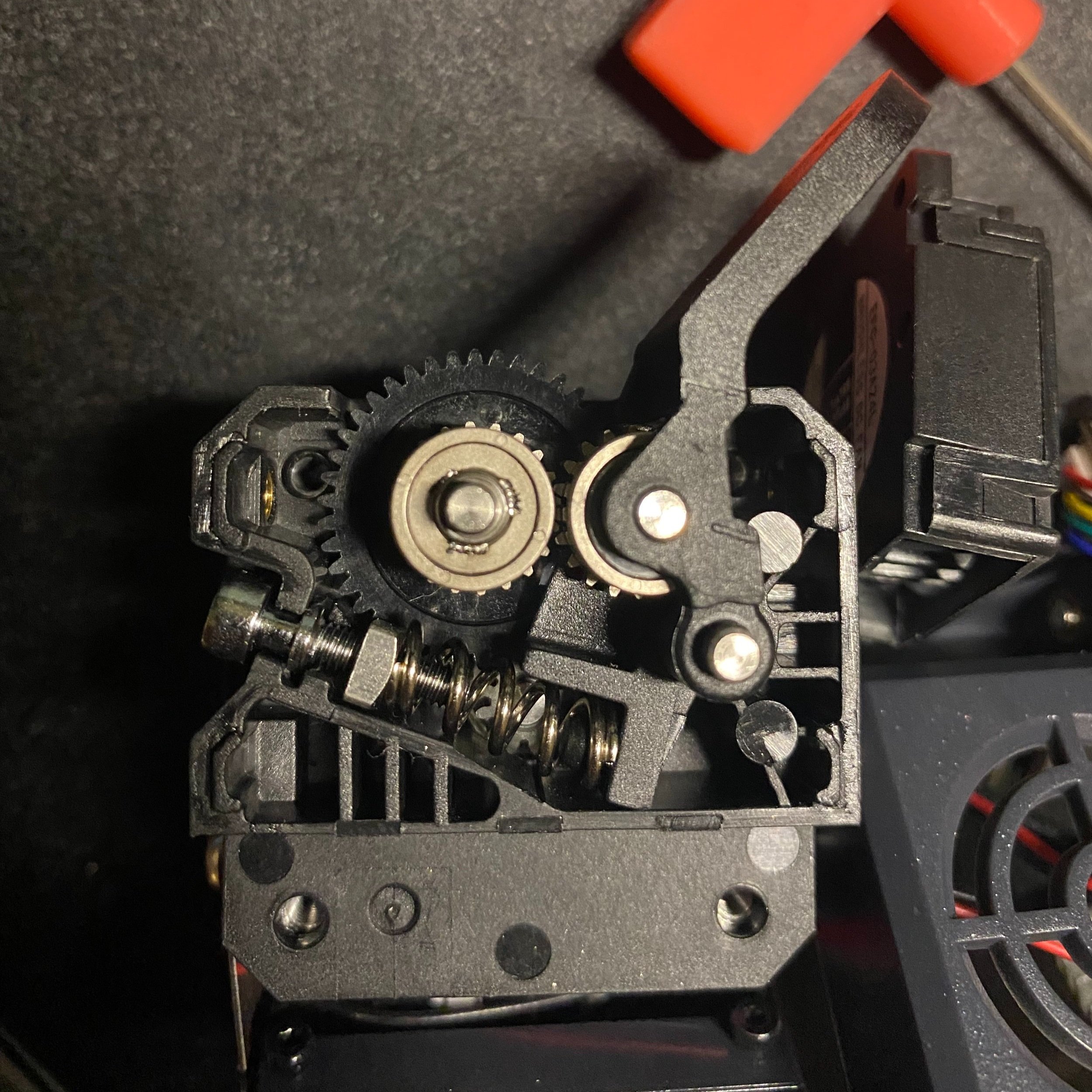
The dual gear extruder assembly pushes the filament from both sides, and uses gearing to achieve more torque and control.
Final Thoughts
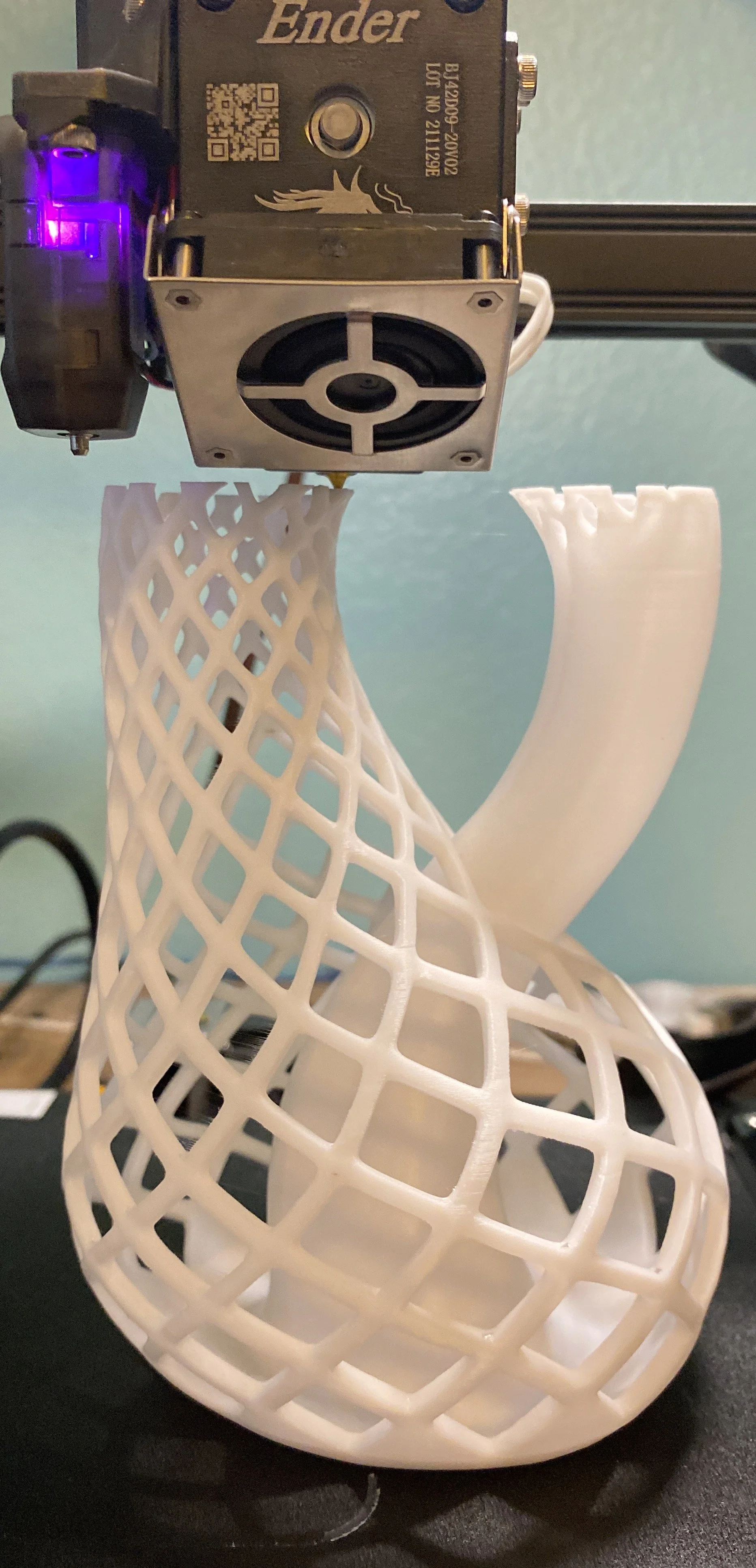
This hot end did really well with a difficult test of overhangs and many small features.
Overall, the “Sprite” hot end looks well-constructed. It is somewhat complex to disassemble, but we don’t anticipate needing to go any further than removing the heat sink to perform maintenance on the hot end. We also liked the seperated PTFE tubes, which will reduce jamming in the hot end. We are hopeful that as the Ender 3 S1 becomes more popular, sellers will start providing replacement thermistors and heater cartridges that have the short cabling, which will make installing replacement parts very simple.
We haven’t had a chance to complete a full set of printing tests with this hot end yet, but we have gotten promising results so far, especially with flexible filaments. We also found that stringing and overhang performance were superior to our other Creality 3D printers. Based on our initial impressions, this new hot end offers some substantial benefits over the Bowden setup on the Ender 3 V2, and goes a long way toward justifying the additional cost of the Ender 3 S1.