
Creality Sprite Extruder Pro Upgrade Install Guide
In this article, we’ll explain how to install the Creality Extruder Pro Kit upgrade on a Creality Ender 3 V2. We’ll go through the entire installation and calibration procedure for the new extruder. Whether you’ve already purchased the Sprite upgrade kit or are just curious about the installation difficulty, this guide should help you see what is involved.
The Sprite Pro upgrade kit works on several Creality 3D Printers, such as the following:
Ender 3
Ender 3 Pro
Ender 3 V2
Ender 3 S1 (already has a Sprite extruder, but the all-metal hot end in this kit is only found on the S1 Pro, not the regular S1)
Ender 3 Max
CR-10 Smart Pro
If you’re installing it on one of those printers, the overall process should be the same, but you may notice a few slight differences during the installation.
Note: Creality Experts receives a commission for items you purchase from this page, at no additional cost to you. For more information, please see our affiliate link policy.
Why Install the Sprite Extruder?
The Sprite extruder [Amazon link] was first introduced on the Ender 3 S1 and is Creality’s first direct-drive extruder. In contrast to the Bowden-style extruder which pushes filament through a long tube to the hot end, the Sprite combines the extruder and hot end into a single assembly. This approach makes the Sprite more reliable and less likely to jam than Creality’s other extruders and hot ends, as well as making it better suited to printing with flexible materials such as TPU. In our experience, the Sprite extruder is noticeably more reliable than our other Creality extruders, making it a worthwhile upgrade.
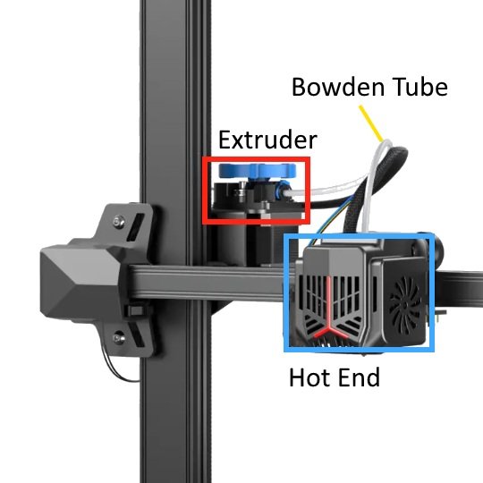
Many Creality 3D printers use a bowden style extruder, with a tube between the extruder and hot-end
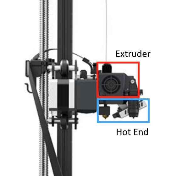
The Sprite extruder is direct drive, where both the extruder and hot end are combined into a single assembly
Additionally, the version of the Sprite that Creality sells in this upgrade kit is the Sprite Pro, which features an all-metal hot end that can heat up to 300 degrees Celsius. This enables you to print higher-temperature materials, such as nylon.
You can find the Creality Sprite Extruder Pro upgrade kit on Amazon here.
Installing the Creality Sprite Extruder Pro Upgrade
The Sprite Pro upgrade kit comes with everything you need to upgrade the extruder and hot end on your Creality printer.
The installation process for the Sprite upgrade is not particularly challenging, although there are a few parts where you will need to be careful to ensure the upgrade goes smoothly. We’ll walk you through the entire process, which involves three main phases. First, you’ll physically install the Sprite on your 3D printer, then you’ll connect the wiring to the printer’s motherboard, and finally, you’ll configure the printer settings and try a test print.
Phase 1: Physical Installation
First, you’ll need to remove the old hot end, extruder, and X carriage from your printer.
Remove the extruder and extruder motor from the printer. On most Creality 3D printers, this will be located on the back of the printer on the left side, attached to the X axis crossbar. You can unscrew the bolts holding the extruder onto the extruder motor, and after you unplug the extruder motor, you can remove both parts from the printer.
The next few steps involve removing the existing X carriage from the printer, because you will need to install the new X carriage provided with the Sprite Pro upgrade kit. This process may vary slightly depending on your printer; we are using a Creality Ender 3 V2 here.
You’ll need to loosen the X belt, which will require loosening the X tensioner (on some models) and removing the idler bracket (all models).
After loosening the X belt, slide the ends of the belt out from the notches on the X carriage to release the carriage.
Begin by loosening the rubber X axis belt that allows the X motor to move the X carriage. On the Ender 3 V2, you need to loosen the blue belt tensioner. On other Creality printers, you may need to loosen a bracket on the right side of the X crossbar.
Locate the ends of the rubber belt where they are pressed into the back of the X carriage. Slide them out toward the back of the printer to disconnect the belt and free the X carriage.
You will need to slide the X carriage off the end of the X crossbar on the right side of the printer. This will vary on your printer model, but you will likely need to unscrew a bracket to allow the carriage to slide off the end of the crossbar. On the Ender 3 V2, I needed to unscrew the crossbar on the right side of the printer, and use my free hand to gently press the crossbar away from the bracket to allow the X carriage to slip past it.
To remove the X carriage, you’ll likely need to unscrew the X crossbar from the bracket on the right side of the printer. You may need to gently pull the X crossbar away from the printer to make a gap large enough for the X carriage to slide off the crossbar.
Next, you’ll need to install the new X carriage and reconnect the X axis belt.
When installed properly, the bracket protruding from the carriage will face toward the front of the printer. Note that the 2 rubber wheels are on the top side of the X crossbar.
In the same way you removed the old X carriage, slide the new X carriage onto the X axis crossbar. The bracket protruding from the carriage should face forward, and the two rubber wheels should be on top.
Re-secure any brackets you removed previously to allow you to remove and install the X carriage.
It is likely that the rubber wheels on the new carriage will be loose and won’t grip the X axis crossbar properly. If so, you can use a wrench (included with the printer) to twist the hexagonal eccentric nut on the bottom of the carriage. This will move the rubber wheels closer together or farther apart, allowing you to adjust how tightly the X carriage grips the X axis crossbar. Adjust the nut until the carriage stays on the X axis crossbar securely without wobbling.
Press the two ends of the X belt into the new X carriage similar to how they were secured to the previous X carriage. Note that the new X carriage has two slots on one side, so you can pick the slot that fits the length of your X axis belt best.
Tighten the X axis belt using the belt tensioner or idler bracket, depending on your printer model. The belt should be taut, but not so tight that the carriage is hard to move along the X axis.
If the X carriage is loose on the crossbar, you can tighten the eccentric nut (hexagonal shape, in between the wheel and carriage) to move the wheel upward to grip the crossbar more securely.
The X carriage contains notches to secure the X belt, similar to the existing carriage on the printer. Note that one side contains two notches, so you can pick the one that fits the length of your X belt best.
Finally, you will need to attach the Sprite extruder and hot end assembly to the X carriage.
Make sure to plug the red heater cable in before installing the Sprite.
The Sprite extruder comes with a tag on the red heater cable indicating that it needs to be plugged in before installation. Remove this tag from the wire and plug the red heater connector into the corresponding plug on the extruder circuit board.
Line up the extruder body with the 4 bolt holes on the X carriage and use the included bolts to secure the extruder to the X carriage.
This completes the physical installation of the Sprite Pro extruder. In the next phase, you’ll connect the wiring for the extruder and hot end.
The Sprite Pro extruder, installed on the X carriage. Note the 4 bolts which secure the extruder to the bracket on the carriage.
Phase 2: Wiring
First, you will need to access the motherboard of the printer and disconnect the wires for the old extruder and hot end.
From the bottom of the printer, you can access the motherboard by removing the bolts on the cover. Look for the spot where the hot end wire harness and LCD ribbon cable disappear.
Ensure the 3D printer is unplugged from power.
Turn the printer over and locate the motherboard access panel. It will typically be secured with a few bolts and you will notice the wiring harness for the printer going into that area of the body. Remove the bolts to access the motherboard. Note that there is a bolt on the top side under the bed for some models
Refer to the manual that comes with the Sprite extruder upgrade, which contains a diagram of the motherboard with all of the connections you need to replace. You will need to disconnect those connectors and wires from the motherboard, so you can connect the wires for the Sprite Pro in their place. See these notes for help removing the connections:
A. For connections that are plugged in, be sure to remove the glue securing the connector to the plug on the motherboard. You can use a utility knife or the clippers included with your printer to carefully cut through the glue. Don’t force the connections, because you could damage the motherboard.
B. For screw terminal connections, loosen the screw and gently pull the wire out from the terminal.Once you have disconnected the wires, you should be able to remove the hot end wires by pulling them from the hot end through the mesh wire harness. The extruder motor wire is likely part of a different wire harness and will remain inside the printer case.
Motherboard wiring diagram for the Sprite extruder kit.
Next, you will need to connect the wires for the Sprite extruder to the motherboard.
Examine the wire harness that comes with the Sprite extruder kit and note that one end has several labeled connectors and wires. This is the end you will connect to the motherboard. Carefully route the wire harness around the printer and toward the motherboard, similar to how the existing wire harnesses are routed.
Refer to the diagram in the instructions to determine where to plug each connection in.
It is critical that you pay attention to the positive and negative labels on the heater wires. If you connect these wires backwards, the hot end will not function and could damage the printer or hot end. Pay attention to the labels on the wires and in the manual to connect the positive and negative wires to the correct screw terminals.
On screw terminal connections, ensure the wire is inserted fully into the screw terminal so that none of the wire is exposed outside the screw terminal.
Once all of the wires are connected, you can replace the motherboard cover and bolts.
The wire harness for the Sprite includes several connectors that need to be attached to the motherboard. Fortunately, they’re all labeled.
For wire terminal connections, be sure to insert the wire completely into the screw terminal and tighten the screw to prevent the wire from slipping out.
Finally, you need to connect the wiring harness to the Sprite extruder.
Turn the printer back upright and locate the ribbon cable connector on the top of the Sprite extruder body. Gently press the connector on the wire harness in and make sure the plastic latches lock in place.
The extruder side of the wire harness is much simpler, with only a single ribbon connector to attach.
Phase 3: Configuration and Testing
Now that you have completed the installation process, you need to configure and test the Sprite extruder and hot end. First, you will need to set the e-steps value for the Sprite extruder.
Navigate to Control -> Motion -> Steps/mm, and adjust the Esteps/mm value to 424.9. Then navigate back to the Control menu, select Store Settings, and hit Enter.
On some printers, such as the Ender 3 V2, the printer will not allow you to set the e-steps value this high. For those printers, follow these steps:
On your computer, create a new text file with the contents:
M92 E424.9
M500
Save this file as “esteps.gcode” and save it to a microSD card to put in your printer.Insert the microSD card into your printer. Use the menu to select the esteps.gcode file and press Print.
When this file completes printing, which should be instant, the e-steps value will be set and saved to the printer’s memory. You can remove the esteps.gcode file from the microSD card.
Next, you will need to re-level the bed and test the hot end.
Since you have installed a new hot end, you will need to re-level the print bed. If you are unsure of how to level the bed, please refer to our bed leveling guide.
Heat the nozzle by navigating to Prepare » Preheat PLA. Watch the temperature display on the printer and confirm that it heats up to the chosen temperature and maintains it. This confirms that the hot end is wired properly.
Load filament into the extruder. On the Sprite extruder, you can use a finger to pull back on the spring-loaded lever, which will allow you to push filament all the way through the hot end to the nozzle.
Navigate to Prepare » Move Axis and move the Extruder axis to confirm the extruder feeds filament properly.
Finally, you are ready to try a test print.
In your slicer software, be sure to change your retraction settings, because they will be much different than what you used on the Bowden extruder. For the Sprite extruder, we recommend starting with 0.6mm retraction distance, 0.0mm extra restart distance, and 85 mm/s speed.
Slice a model with the new settings and print it to ensure everything works properly.
This completes the upgrade process for the Sprite Pro. Enjoy your new upgraded 3D printer!
Click here to view the Creality Sprite Extruder Pro upgrade kit on Amazon.